Dc Motor Driver Schematic
Schematic controller brushless motor circuit esc dc schematics hall phase sensor board make eagle used simple motors 3phase digital Pwm motor dc controller circuit ne555 diagram darlington transistors 555 dimmer led power using transistor voltage generator switch eleccircuit battery Dc-motor driver circuits
Bldc Motor Wiring Diagram - Wiring Diagram and Schematic Role
Motor dc circuit controller driver schematic amp diagram simple control using rangkaian bidirectional directional bi direction op speed make throttle Dc motor driver bridge transistor circuit control diagram using circuits relay old How to rotate dc motor in both direction
Brushless motor dc control esc bldc phase circuit schematic introduction drive motors speed pwm proteus without sensing electronic phases microcontroller
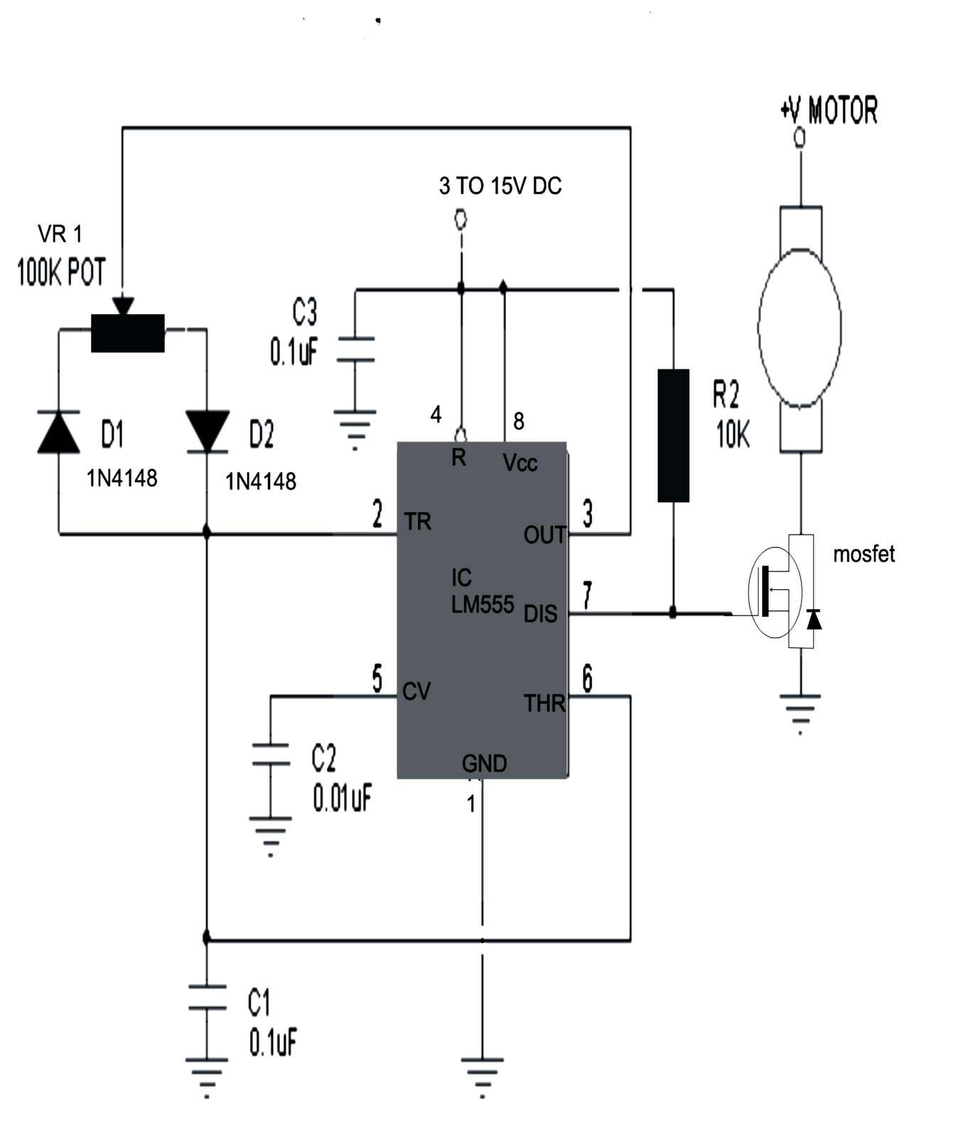
Motor dc speed controller circuit diagram simplest555 pwm dc motor controller circuit An introduction to brushless dc motor controlMotor dc circuit driver channel model direction saving both eleccircuit control speed rotate circuits directions transistors drive driving article.
Motor l293 microcontroller dc interfacing driver using pic ic schematic why“3 phase brushless dc motor” “3 phase brushless dc motor controller Arduino: pic microcontroller interfacing with dc motor via l293dMotor circuit arduino brushless dc bldc controller diagram simple esc control sensorless diy wiring using schematic projects ir2110 speed code.

Motor circuit dc speed pwm controller control simple circuits diagram brushed based ic schematic mosfet 555 24vdc use potentiometer build
Dc brake ampMake this pwm based dc motor speed controller circuit Simplest dc motor speed controller circuit diagramBldc motor wiring diagram.
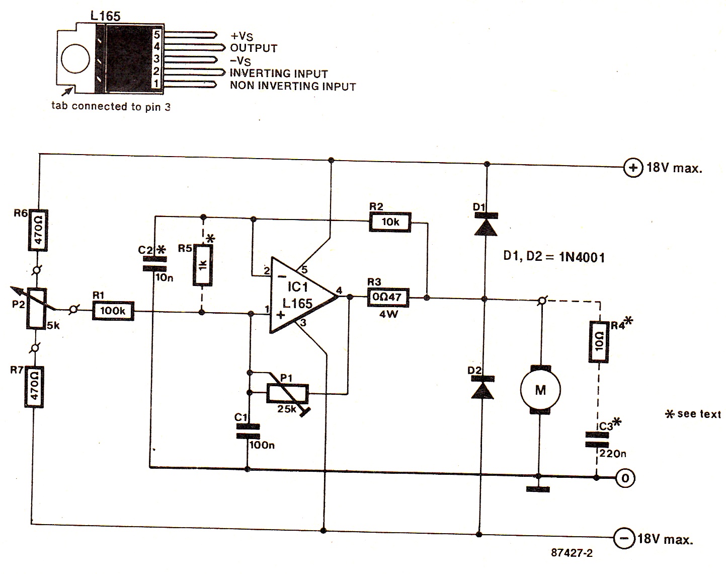
Science and engineering: simple dc motor driver .


